ObjectConnectorDistance
Connector which enforces constant or prescribed distance between two bodies/nodes.
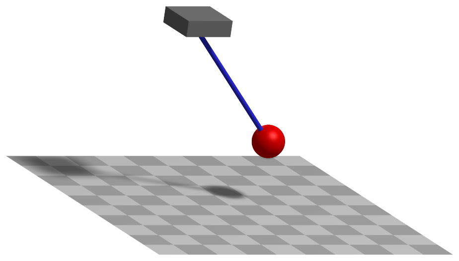
Simpler: mbs.CreateDistanceConstraint adds this item, with what it needs, in one call.
Interface
Python names:
ObjectConnectorDistanceorDistanceConstraint, andVDistanceConstraintfor its visualizationMarkers it acts on: those providing
Position: MarkerBodyPosition, MarkerBodyRigid, MarkerNodePosition, MarkerNodeRigid, MarkerSuperElementPosition, MarkerSuperElementRigid, MarkerKinematicTreeRigid
Parameters
The parameters of the item; in a dictionary, its type is ‘ConnectorDistance’:
name |
type |
size |
default |
description |
|---|---|---|---|---|
name |
String |
‘’ |
constraints’s unique name |
|
markerNumbers |
ArrayMarkerIndex |
[ invalid (-1), invalid (-1) ] |
(symbol: \([m0,m1]\tp\)) list of markers used in connector |
|
distance |
PReal |
0. |
(symbol: \(d_0\)) prescribed distance [SI:m] of the used markers; must by greater than zero; must be given: the default is only a placeholder |
|
activeConnector |
Bool |
True |
flag, which determines, if the connector is active; used to deactivate (temporarily) a connector or constraint |
|
visualization |
VObjectConnectorDistance |
parameters for visualization of item |
Visualization parameters
The parameters of VObjectConnectorDistance, given as visualization:
name |
type |
size |
default |
description |
|---|---|---|---|---|
show |
Bool |
True |
set true, if item is shown in visualization and false if it is not shown |
|
drawSize |
float |
-1. |
the diameter of the rod drawn between the markers if visualizationSettings.connectors.drawSimplified is False; -1 means a tenth of connectors.defaultSize; with drawSimplified, the connector is a line |
|
color |
Float4 |
4 |
[-1.,-1.,-1.,-1.] |
RGBA connector color; if R==-1, use default color |
Drawing
Drawn as all constraints; a line between the markers with connectors.drawSimplified, otherwise a rod of diameter drawSize.
Settings beyond those of all constraints: connectors.drawSimplified, general.cylinderTiling.
Output variables
Available as OutputVariableType in sensors, Get...Output() and other functions:
output variable |
symbol |
description |
|---|---|---|
Displacement |
\(\LU{0}{\Delta\pv}\) |
relative displacement in global coordinates |
Velocity |
\(\LU{0}{\Delta\vv}\) |
relative translational velocity in global coordinates |
Distance |
\(\vert \LU{0}{\Delta\pv}\vert \) |
distance between markers (should stay constant; shows constraint deviation) |
Force |
\(\lambda_0\) |
joint force (=scalar Lagrange multiplier) |
Detailed description
Definition of quantities
intermediate variables |
symbol |
description |
|---|---|---|
marker m0 position |
\(\LU{0}{\pv}_{m0}\) |
current global position which is provided by marker m0 |
marker m1 position |
\(\LU{0}{\pv}_{m1}\) |
accordingly |
marker m0 velocity |
\(\LU{0}{\vv}_{m0}\) |
current global velocity which is provided by marker m0 |
marker m1 velocity |
\(\LU{0}{\vv}_{m1}\) |
accordingly |
relative displacement |
\(\LU{0}{\Delta\pv}\) |
\(\LU{0}{\pv}_{m1} - \LU{0}{\pv}_{m0}\) |
relative velocity |
\(\LU{0}{\Delta\vv}\) |
\(\LU{0}{\vv}_{m1} - \LU{0}{\vv}_{m0}\) |
algebraicVariable |
\(\lambda_0\) |
Lagrange multiplier = force in constraint |
Connector constraint equations
If activeConnector = True, the index 3 algebraic equation reads
Due to the fact that the force direction is given by
the prescribed distance \(d_0\) may not be zero. This would, otherwise, result in a change of the number of constraints. The index 2 (velocity level) algebraic equation reads
if activeConnector = False, the algebraic equation reads
Mini example
#example with 1m pendulum, 50kg under gravity
nMass = mbs.AddNode(NodePoint2D(referenceCoordinates=[1,0]))
oMass = mbs.AddObject(MassPoint2D(mass = 50, nodeNumber = nMass))

mMass = mbs.AddMarker(MarkerNodePosition(nodeNumber=nMass))
mGround = mbs.AddMarker(MarkerBodyPosition(bodyNumber=oGround, localPosition = [0,0,0]))
oDistance = mbs.AddObject(DistanceConstraint(markerNumbers = [mGround, mMass], distance = 1))

mbs.AddLoad(Force(markerNumber = mMass, loadVector = [0, -50*9.81, 0]))

#assemble and solve system for default parameters
mbs.Assemble()

sims=exu.SimulationSettings()
sims.timeIntegration.generalizedAlpha.spectralRadius=0.7
mbs.SolveDynamic(sims)

#check result at default integration time
exu.sys['testResult'] = mbs.GetNodeOutput(nMass, exu.OutputVariableType.Position)[0]
Examples (Ex) and TestModels (TM) that show this item, with weblink to github: pendulum2Dconstraint.py (Ex), MathematicalPendulumTest.py (TM), fourBarMechanismTest.py (TM)