ObjectJointALEMoving2D
A specialized axially moving joint (without rotation) in 2D between a ALE Cable2D (marker1) and a position-based marker (marker0); ALE=Arbitrary Lagrangian Eulerian; the data coordinate x[0] provides the current index in slidingMarkerNumbers, and the ODE2 coordinate q[0] provides the (given) moving coordinate in the cable element.
Interface
Python names:
ObjectJointALEMoving2DorALEMovingJoint2D, andVALEMovingJoint2Dfor its visualizationNodes: see the detailed description
Parameters
The parameters of the item; in a dictionary, its type is ‘JointALEMoving2D’:
name |
type |
size |
default |
description |
|---|---|---|---|---|
name |
String |
‘’ |
constraints’s unique name |
|
markerNumbers |
ArrayMarkerIndex |
[ invalid (-1), invalid (-1) ] |
(symbol: \([m0,\,m1]\tp\)) marker m0: position-marker of mass point or rigid body; marker m1: updated marker to ANCF Cable2D element, where the sliding joint currently is attached to; must be initialized with an appropriate (global) marker number according to the starting position of the sliding object; this marker changes with time (PostNewtonStep) |
|
slidingMarkerNumbers |
ArrayMarkerIndex |
[] |
(symbol: \([m_{s0}, \ldots, m_{sn}]\tp\)) a list of sn (global) marker numbers which are are used to update marker1 |
|
slidingMarkerOffsets |
Vector |
[] |
(symbol: \([d_{s0}, \ldots, d_{sn}]\)) this list contains the offsets of every sliding object (given by slidingMarkerNumbers) w.r.t. to the initial position (0): marker0: offset=0, marker1: offset=Length(cable0), marker2: offset=Length(cable0)+Length(cable1), … |
|
slidingOffset |
Real |
0. |
(symbol: \(s_\mathrm{off}\)) sliding offset [SI:m]: a scalar offset, which represents the (reference arc) length of all previous sliding cable elements |
|
nodeNumbers |
ArrayNodeIndex |
[ invalid (-1), invalid (-1) ] |
(symbol: \([n_{GD}, n_{ALE}]\)) node number of NodeGenericData (GD) with one data coordinate and of NodeGenericODE2 (ALE) with one ODE2 coordinate |
|
usePenaltyFormulation |
Bool |
False |
flag, which determines, if the connector is formulated with penalty, but still using algebraic equations (IsPenaltyConnector() still false) |
|
penaltyStiffness |
Real |
0. |
(symbol: \(k\)) penalty stiffness [SI:N/m] used if usePenaltyFormulation=True |
|
activeConnector |
Bool |
True |
flag, which determines, if the connector is active; used to deactivate (temporarily) a connector or constraint |
|
visualization |
VObjectJointALEMoving2D |
parameters for visualization of item |
Visualization parameters
The parameters of VObjectJointALEMoving2D, given as visualization:
name |
type |
size |
default |
description |
|---|---|---|---|---|
show |
Bool |
True |
set true, if item is shown in visualization and false if it is not shown |
|
drawSize |
float |
-1. |
drawing size = radius of revolute joint; size == -1.f means that default connector size is used |
|
color |
Float4 |
4 |
[-1.,-1.,-1.,-1.] |
RGBA connector color; if R==-1, use default color |
Drawing
Drawn as all joints; a circle of diameter drawSize at marker 0 and at the sliding position, with a cross there.
Output variables
Available as OutputVariableType in sensors, Get...Output() and other functions:
output variable |
symbol |
description |
|---|---|---|
Position |
\(\LU{0}{\pv}_{m0}\) |
current global position of position marker \(m0\) |
Velocity |
\(\LU{0}{\vv}_{m0}\) |
current global velocity of position marker \(m0\) |
SlidingCoordinate |
\(s_g = q_{ALE} + s_\mathrm{off}\) |
current value of the global sliding ALE coordinate, including offset; note that reference coordinate of \(q_{ALE}\) is ignored! |
Coordinates |
\([x_{data0},\,q_{ALE}]\tp\) |
provides two values: [0] = current sliding marker index, [1] = ALE sliding coordinate |
Coordinates_t |
\([\dot q_{ALE}]\tp\) |
provides ALE sliding velocity |
Force |
\(\fv\) |
joint force vector (3D) |
Detailed description
Definition of quantities
intermediate variables |
symbol |
description |
|---|---|---|
generic data node |
\(\xv=[x_{data0}]\tp\) |
coordinates of node with node number \(n_{GD}\) |
generic ODE2 node |
\(\qv=[q_{0}]\tp\) |
coordinates of node with node number \(n_{ALE}\), which is shared with all ALE-ANCF and ALE sliding joint objects |
data coordinate |
\(x_{data0}\) |
the current index in slidingMarkerNumbers |
ALE coordinate |
\(q_{ALE} = q_{0}\) |
current ALE coordinate (in fact this is the Eulerian coordinate in the ALE formulation); note that reference coordinate of \(q_{ALE}\) is ignored! |
marker m0 position |
\(\LU{0}{\pv}_{m0}\) |
current global position which is provided by marker m0 |
marker m0 velocity |
\(\LU{0}{\vv}_{m0}\) |
current global velocity which is provided by marker m0 |
cable coordinates |
\(\qv_{ANCF,m1}\) |
current coordiantes of the ANCF cable element with the current marker \(m1\) is referring to |
sliding position |
\(\LUR{0}{\rv}{ANCF} = \Sm(s_{el})\qv_{ANCF,m1}\) |
current global position at the ANCF cable element, evaluated at local sliding position \(s_{el}\) |
sliding position slope |
\(\LURU{0}{\rv}{ANCF}{\prime} = \Sm^\prime(s_{el})\qv_{ANCF,m1}\) |
current global slope vector of the ANCF cable element, evaluated at local sliding position \(s_{el}\) |
sliding velocity |
\(\LUR{0}{\vv}{ANCF} = \Sm(s_{el})\dot\qv_{ANCF,m1} + \dot q_{ALE} \LURU{0}{\rv}{ANCF}{\prime}\) |
current global velocity at the ANCF cable element, evaluated at local sliding position \(s_{el}\), including convective term |
sliding normal vector |
\(\LU{0}{\nv} = [-r^\prime_1,\,r^\prime_0]\) |
2D normal vector computed from slope \(\rv^\prime=\LURU{0}{\rv}{ANCF}{\prime}\) |
algebraic variables |
\(\zv=[\lambda_0,\,\lambda_1]\tp\) |
algebraic variables (Lagrange multipliers) according to the algebraic equations |
Geometric relations
The element sliding coordinate (in the local coordinates of the current sliding element) is computed from the ALE coordinate
For the description of the according quantities, see the description above. The distance \(d_{m1}\) is obtained from the slidingMarkerOffsets list, using the current (local) index \(x_{data0}\).
The vector (=difference; error) between the marker \(m0\) and the marker \(m1\) (=\(\rv_{ANCF}\)) positions reads
Note that \(\LU{0}{\pv}_{m0}\) represents the current position of the marker \(m0\), which could represent the midpoint of a mass sliding along the beam.
The position \(\LUR{0}{\rv}{ANCF}\) is computed from the beam represented by marker \(m1\), using the local beam coordinate \(x=s_{el}\).
The marker and the according beam finite element changes during movement using the list slidingMarkerNumbers and the index is updated in the PostNewtonStep.
The vector (=difference; error) between the marker \(m0\) and the marker \(m1\) velocities reads
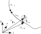
Fig. 45 Geometrical relations for ALE sliding joint.
Connector constraint equations
The 2D sliding joint is implemented having 2 equations, using the Lagrange multipliers \(\zv\). The algebraic (index 3) equations read
Note that the Lagrange multipliers \([\lambda_0,\,\lambda_1]\tp\)are the global forces in the joint. In the index 2 case the algebraic equations read
If usePenalty = True, the algebraic equations are changed to:
If activeConnector = False, the algebraic equations are changed to:
Post Newton Step
After the Newton solver has converged, a PostNewtonStep is performed for the element, which updates the marker \(m1\) index if necessary.
Furthermore, it is checked, if \(x_{data0}\) becomes smaller than zero, which raises a warning and keeps \(x_{data0}=0\). The same results if \(x_{data0}\ge sn\), then \(x_{data0} = sn\). Finally, the data coordinate is updated in order to provide the starting value for the next step,
Mini example
from exudyn.beams import GenerateBeamElementsAlongLine
#a mass point carried by the material of an axially moving cable
nALE = mbs.AddNode(NodeGenericODE2(numberOfODE2Coordinates=1, referenceCoordinates=[0],
                                   initialCoordinates=[0], initialCoordinates_t=[0]))
cable = ObjectALEANCFCable2D(massPerLength=1, bendingStiffness=10, axialStiffness=1e4)
cable.nodeNumbers[2] = nALE
beamInfo = GenerateBeamElementsAlongLine(mbs, positionStart=[0,0,0], positionEnd=[2,0,0],
                        numberOfElements=4, beamTemplate=cable,
                        groundConstraintsStart=[1,1,1,1], groundConstraintsEnd=[1,1,1,1])
nodes, elements = beamInfo['nodes'], beamInfo['elements']
mbs.AddLoad(LoadCoordinate(markerNumber=mbs.AddMarker(MarkerNodeCoordinate(nodeNumber=nALE, coordinate=0)), load=1))

nMass = mbs.AddNode(NodePoint2D(referenceCoordinates=[0.6,0]))
mbs.AddObject(ObjectMassPoint2D(nodeNumber=nMass, mass=2))
cableMarkers = [mbs.AddMarker(MarkerBodyCable2DCoordinates(bodyNumber=e)) for e in elements]
nData = mbs.AddNode(NodeGenericData(numberOfDataCoordinates=1, initialCoordinates=[1])) #element 1
mbs.AddObject(ObjectJointALEMoving2D(markerNumbers=[mbs.AddMarker(MarkerNodePosition(nodeNumber=nMass)), cableMarkers[1]],
                                     slidingMarkerNumbers=cableMarkers, slidingMarkerOffsets=[0.5*i for i in range(4)],
                                     slidingOffset=0.6, nodeNumbers=[nData, nALE]))

mbs.Assemble()
mbs.SolveDynamic()

#cable material (mass 2) and mass point (2) move together: x = 0.6 + F/(2*4)*t^2 at t=1
exu.sys['testResult'] = mbs.GetNodeOutput(nMass, exu.OutputVariableType.Position)[0] #0.725
Relevant Examples (Ex) and TestModels (TM) with weblink to github: ANCFmovingRigidbody.py (Ex), ANCFmovingRigidBodyTest.py (TM)