ObjectJointRollingDisc
A joint representing a rolling rigid disc (marker 1) on a flat surface (marker 0, ground body) in global \(x\)-\(y\) plane. The contraint is based on an idealized rolling formulation with no slip. The contraints works for discs as long as the disc axis and the plane normal vector are not parallel. It must be assured that the disc has contact to ground in the initial configuration (adjust z-position of body accordingly). The ground body can be a rigid body which is moving. In this case, the flat surface is assumed to be in the \(x\)-\(y\)-plane at \(z=0\). Note that the rolling body must have the reference point at the center of the disc. NOTE: the cases of normal other than \(z\)-direction, wheel axis other than \(x\)-axis and moving ground body needs to be tested further, check your results!
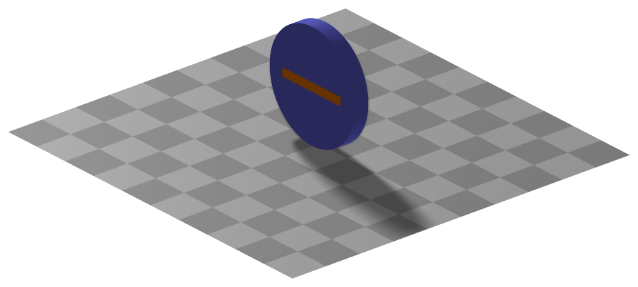
Simpler: mbs.CreateRollingDisc adds this item, with what it needs, in one call.
Interface
Python names:
ObjectJointRollingDiscorRollingDiscJoint, andVRollingDiscJointfor its visualizationMarkers it acts on: those providing
PositionandOrientation: MarkerBodyRigid, MarkerNodeRigid, MarkerSuperElementRigid, MarkerKinematicTreeRigid
Parameters
The parameters of the item; in a dictionary, its type is ‘JointRollingDisc’:
name |
type |
size |
default |
description |
|---|---|---|---|---|
name |
String |
‘’ |
constraints’s unique name |
|
markerNumbers |
ArrayMarkerIndex |
2 |
[ invalid (-1), invalid (-1) ] |
(symbol: \([m0,m1]\tp\)) list of markers used in connector; \(m0\) represents the ground and \(m1\) represents the rolling body, which has its reference point (=local position [0,0,0]) at the disc center point |
constrainedAxes |
ArrayIndex |
3 |
[1,1,1] |
(symbol: \(\jv=[j_0,\,\ldots,\,j_2]\)) flags, which determine which constraints are active, in which \(j_0\) represents lateral motion, \(j_1\) longitudinal (forward/backward) motion and \(j_2\) represents the normal (contact) direction |
activeConnector |
Bool |
True |
flag, which determines, if the connector is active; used to deactivate (temporarily) a connector or constraint |
|
discRadius |
PReal |
0 |
defines the disc radius; must be given: the default is only a placeholder |
|
discAxis |
Vector3D |
3 |
[1,0,0] |
(symbol: \(\LU{m1}{\wv_{1}}, \;\; \vert \LU{m1}{\wv_{1}}\vert = 1\)) axis of disc defined in marker \(m1\) frame |
planeNormal |
Vector3D |
3 |
[0,0,1] |
(symbol: \(\LU{m0}{\vv_{PN}}\)) normal to the contact / rolling plane defined in marker \(m0\) coordinates |
visualization |
VObjectJointRollingDisc |
parameters for visualization of item |
Visualization parameters
The parameters of VObjectJointRollingDisc, given as visualization:
name |
type |
size |
default |
description |
|---|---|---|---|---|
show |
Bool |
True |
set true, if item is shown in visualization and false if it is not shown |
|
discWidth |
float |
0.1 |
width of disc for drawing |
|
color |
Float4 |
4 |
[-1.,-1.,-1.,-1.] |
RGBA connector color; if R==-1, use default color |
Drawing
Drawn as all joints; the disc of width discWidth, with 4 times general.cylinderTiling segments, and its axis.
Settings beyond those of all joints: general.cylinderTiling.
Output variables
Available as OutputVariableType in sensors, Get...Output() and other functions:
output variable |
symbol |
description |
|---|---|---|
Position |
\(\LU{0}{\pv}_{G}\) |
current global position of contact point between rolling disc and ground |
Velocity |
\(\LU{0}{\vv}_{trail}\) |
current velocity of the trail (according to motion of the contact point along the trail!) in global coordinates; this is not the velocity of the contact point; needs further testing for general case of relative moving bodies |
ForceLocal |
\(\LU{J1}{\fv} = \LU{0}{[f_0,\, f_1,\, f_2]\tp}= [-\zv^T \LU{0}{\wv_{lat}}, \, -\zv^T \LU{0}{\wv_2}, \, -\zv^T \LU{0}{\vv_{PN}}]\tp\) |
contact forces acting on disc, in special \(J1\) joint coordinates, \(f_0\) being the lateral force (parallel to ground plane), \(f_1\) being the longitudinal force and \(f_2\) being the normal force |
RotationMatrix |
\(\LU{0,J1}{\Am} = [\LU{0}{\wv_{lat}},\, \LU{0}{\wv}_2,\, \LU{0}{\vv_{PN}}]\) |
transformation matrix of special joint coordinates \(J1\) to global coordinates |
Detailed description
Definition of quantities
intermediate variables |
symbol |
description |
|---|---|---|
marker m0 position |
\(\LU{0}{\pv}_{m0}\) |
current global position of marker \(m0\); needed only if body \(m0\) is not a ground body |
marker m0 orientation |
\(\LU{0,m0}{\Rot}\) |
current rotation matrix provided by marker m0 (assumed to be rigid body) |
marker m0 velocity |
\(\LU{0}{\vv}_{m0}\) |
current global velocity which is provided by marker m0 (assumed to be rigid body) |
marker m0 angular velocity |
\(\LU{0}{\tomega}_{m0}\) |
current angular velocity vector provided by marker m0 (assumed to be rigid body) |
marker m1 position |
\(\LU{0}{\pv}_{m1}\) |
center of disc |
marker m1 orientation |
\(\LU{0,m1}{\Rot}\) |
current rotation matrix provided by marker m1 |
marker m1 velocity |
\(\LU{0}{\vv}_{m1}\) |
accordingly |
marker m1 angular velocity |
\(\LU{0}{\tomega}_{m1}\) |
current angular velocity vector provided by marker m1 |
ground normal vector |
\(\LU{0}{\vv_{PN}} = \LU{0,m0}{\Am} \LU{m0}{\vv_{PN}}\) |
normalized normal vector to the ground plane, moving with marker \(m0\) |
ground position B |
\(\LU{0}{\pv}_{B}\) |
disc center point projected on ground in plane normal (\(z\)-direction, \(z=0\)) |
ground position C |
\(\LU{0}{\pv}_{C}\) |
contact point of disc with ground in global coordinates |
ground velocity C |
\(\LU{0}{\vv}_{Cm1}\) |
velocity of disc (marker 1) at ground contact point (must be zero if ground does not move) |
ground velocity C |
\(\LU{0}{\vv}_{Cm2}\) |
velocity of ground (marker 0) at ground contact point (is always zero if ground does not move) |
wheel axis vector |
\(\LU{0}{\wv_1} =\LU{0,m1}{\Rot} \LU{m1}{\wv_{1}} \) |
normalized disc axis vector |
longitudinal vector |
\(\LU{0}{\wv_2}\) |
vector in longitudinal (motion) direction |
lateral vector |
\(\LU{0}{\wv_{lat}} = \LU{0}{\vv_{PN}} \times \LU{0}{\wv}_2\) |
vector in lateral direction, parallel to ground plane |
contact point vector |
\(\LU{0}{\wv_3}\) |
normalized vector from disc center point in direction of contact point C |
\(D1\) transformation matrix |
\(\LU{0,D1}{\Am} = [\LU{0}{\wv_1},\, \LU{0}{\wv_2},\, \LU{0}{\wv_3}]\) |
transformation of special disc coordinates \(D1\) to global coordinates |
\(J1\) transformation matrix |
\(\LU{0,J1}{\Am} = [\LU{0}{\wv_{lat}},\, \LU{0}{\wv}_2,\, \LU{0}{\vv_{PN}}]\) |
transformation of special joint \(J1\) coordinates to global coordinates |
algebraic variables |
\(\zv=[\lambda_0,\,\lambda_1,\,\lambda_2]\tp\) |
vector of algebraic variables (Lagrange multipliers) according to the algebraic equations |
Geometric relations
The main geometrical setup is shown in the following figure: First, the contact point \(\LU{0}{\pv}_{C}\) must be computed. With the helper vector,
we obtain a disc coordinate system, representing the longitudinal direction,
and the vector to the contact point,
The contact point \(C\) can be computed from
The velocity of the contact point at the disc is computed from,
If marker 0 body is (moving) rigid body instead of a ground body, the contact point \(C\) is reconstructed in body of marker 0,
The velocity of the contact point at the marker 0 body reads
Connector constraint equations
Constraints for activeConnector = True:
The non-holonomic, index 2 constraints for the tangential and normal contact follow from (an index 3 formulation would be possible, but is not implemented yet because of mixing different jacobians)
In case that activeConnector = False, the Lagrange multipliers are set to zero:
Note that since version 1.8.27 the constraints can be turned on/off separately with constrainedAxes=[b0,b1,b2], in which
b0 represents the flag for lateral motion, b1 switches the constraint for forward motion and b2 for motion in plane normal direction.
Mini example
#a disc rolling without slip on the ground plane: the constraint of ideal rolling
r = 0.2
inertia = InertiaCylinder(density=1000, length=0.05, outerRadius=r, axis=0)
node = mbs.AddNode(NodeRigidBodyEP(referenceCoordinates=[0,0,r]+eulerParameters0,
                   initialVelocities=[0,-2,0]+list(AngularVelocity2EulerParameters_t([2/r,0,0], eulerParameters0))))
disc = mbs.AddObject(ObjectRigidBody(nodeNumber=node, mass=inertia.Mass(), inertia=inertia.GetInertia6D()))
mbs.AddLoad(LoadMassProportional(markerNumber=mbs.AddMarker(MarkerBodyMass(bodyNumber=disc)), loadVector=[0,0,-9.81]))
mGround = mbs.AddMarker(MarkerBodyRigid(bodyNumber=oGround, localPosition=[0,0,0]))
mDisc = mbs.AddMarker(MarkerBodyRigid(bodyNumber=disc, localPosition=[0,0,0]))
mbs.AddObject(ObjectJointRollingDisc(markerNumbers=[mGround, mDisc], discRadius=r, discAxis=[1,0,0],
                                     planeNormal=[0,0,1]))

mbs.Assemble()
mbs.SolveDynamic()

#it rolls on with the initial velocity: y = -2*t at t=1
exu.sys['testResult'] = mbs.GetNodeOutput(node, exu.OutputVariableType.Position)[1] #-2
Relevant Examples (Ex) and TestModels (TM) with weblink to github: bicycleIftommBenchmark.py (Ex), reinforcementLearningRobot.py (Ex), rollingCoinTest.py (TM), rollingDiscTangentialForces.py (TM), rotatingTableTest.py (TM), createFunctionsTest.py (TM), createRollingDiscTest.py (TM)