ObjectJointRevoluteZ
A revolute joint in 3D; constrains the position of two rigid body markers and the rotation about two axes, while the joint \(z\)-rotation axis (defined in local coordinates of marker 0 / joint J0 coordinates) can freely rotate. The joint coordinate system is the frame of the markers; a rotation of it is given to the markers as their localHT. For easier definition of the joint, use mbs.CreateRevoluteJoint(...) for two rigid bodies (or ground).
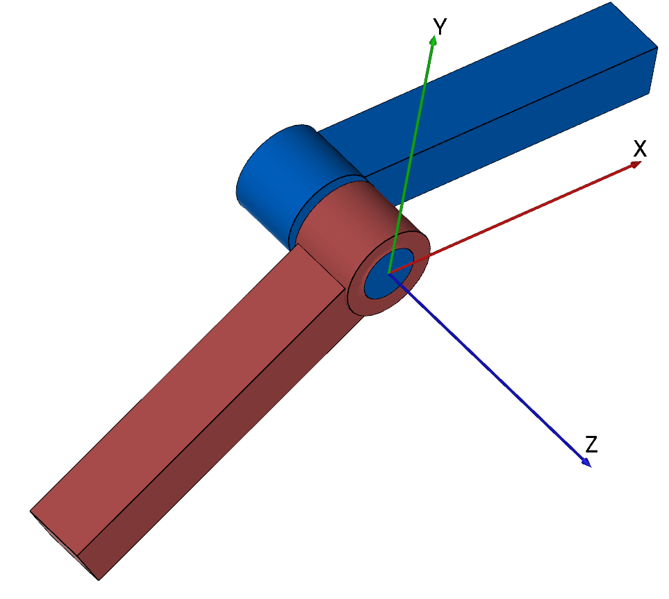
Simpler: mbs.CreateRevoluteJoint adds this item, with what it needs, in one call.
Interface
Python names:
ObjectJointRevoluteZorRevoluteJointZ, andVRevoluteJointZfor its visualizationMarkers it acts on: those providing
PositionandOrientation: MarkerBodyRigid, MarkerNodeRigid, MarkerSuperElementRigid, MarkerKinematicTreeRigid
Parameters
The parameters of the item; in a dictionary, its type is ‘JointRevoluteZ’:
name |
type |
size |
default |
description |
|---|---|---|---|---|
name |
String |
‘’ |
constraints’s unique name |
|
markerNumbers |
ArrayMarkerIndex |
2 |
[ invalid (-1), invalid (-1) ] |
(symbol: \([m0,m1]\tp\)) list of markers used in connector |
rotationMarker0 |
Matrix3D |
9 |
[[1,0,0], [0,1,0], [0,0,1]] |
(symbol: \(\LU{m0,J0}{\Rot}\)) local rotation matrix for marker \(m0\); translation and rotation axes for marker \(m0\) are defined in the local body coordinate system and additionally transformed by rotationMarker0 |
rotationMarker1 |
Matrix3D |
9 |
[[1,0,0], [0,1,0], [0,0,1]] |
(symbol: \(\LU{m1,J1}{\Rot}\)) local rotation matrix for marker \(m1\); translation and rotation axes for marker \(m1\) are defined in the local body coordinate system and additionally transformed by rotationMarker1 |
activeConnector |
Bool |
True |
flag, which determines, if the connector is active; used to deactivate (temporarily) a connector or constraint |
|
visualization |
VObjectJointRevoluteZ |
parameters for visualization of item |
Deprecated parameters, which still work and give a DeprecationWarning when set other than their default: rotationMarker0 (deprecated since 1.12.244, removed in 2031): give the rotation to marker 0 as its localHT, e.g. MarkerBodyRigid(bodyNumber=b, localHT=exu.HT(rotation=A, translation=p)); rotationMarker1 (deprecated since 1.12.244, removed in 2031): give the rotation to marker 1 as its localHT, e.g. MarkerBodyRigid(bodyNumber=b, localHT=exu.HT(rotation=A, translation=p)).
Visualization parameters
The parameters of VObjectJointRevoluteZ, given as visualization:
name |
type |
size |
default |
description |
|---|---|---|---|---|
show |
Bool |
True |
set true, if item is shown in visualization and false if it is not shown |
|
axisRadius |
float |
0.1 |
radius of joint axis to draw |
|
axisLength |
float |
0.4 |
length of joint axis to draw |
|
color |
Float4 |
4 |
[-1.,-1.,-1.,-1.] |
RGBA connector color; if R==-1, use default color |
Drawing
Drawn as all joints; the axis as two cylinders of axisRadius and axisLength, the thinner one at marker 0; with connectors.showJointAxes the frames of both markers.
Settings beyond those of all joints: connectors.jointAxesLength, connectors.jointAxesRadius, connectors.showJointAxes, general.axesTiling, general.cylinderTiling.
Output variables
Available as OutputVariableType in sensors, Get...Output() and other functions:
output variable |
symbol |
description |
|---|---|---|
Position |
\(\LU{0}{\pv}_{m0}\) |
current global position of position marker \(m0\) |
Velocity |
\(\LU{0}{\vv}_{m0}\) |
current global velocity of position marker \(m0\) |
DisplacementLocal |
\(\LU{J0}{\Delta\pv}\) |
relative displacement in local joint0 coordinates; uses local J0 coordinates even for spherical joint configuration |
VelocityLocal |
\(\LU{J0}{\Delta\vv}\) |
relative translational velocity in local joint0 coordinates |
Rotation |
\(\LU{J0}{\ttheta}= [\theta_0,\theta_1,\theta_2]\tp\) |
relative rotation parameters (Tait Bryan Rxyz); Z component represents rotation of joint, other components represent constraint drift |
AngularVelocityLocal |
\(\LU{J0}{\Delta\tomega}\) |
relative angular velocity in joint J0 coordinates, giving a vector with Z-component only |
ForceLocal |
\(\LU{J0}{\fv}\) |
joint force in local \(J0\) coordinates |
TorqueLocal |
\(\LU{J0}{\mv}\) |
joint torques in local \(J0\) coordinates; torque around Z is zero |
HomogeneousTransformation |
\(\LU{0}{\Hm}_{J0}\) |
the joint frame \(J0\) as homogeneous transformation: its rotation matrix and the position of marker \(m0\), as 4x4 matrix \([\LU{0}{\Rot}_{J0}\;\LU{0}{\pv}_{m0};\;\Null\tp\;1]\); the Get…Output functions return it as exu.HT, a sensor stores its 16 values row by row |
HomogeneousTransformationLocal |
\(\LU{J0}{\Hm}_{J1} = \LU{0}{\Hm}_{J0}^{-1}\,\LU{0}{\Hm}_{J1}\) |
the joint frame \(J1\) relative to the joint frame \(J0\): the relative rotation matrix \(\LU{0}{\Rot}_{J0}\tp\LU{0}{\Rot}_{J1}\) and the relative position \(\LU{0}{\Rot}_{J0}\tp(\LU{0}{\pv}_{m1}-\LU{0}{\pv}_{m0})\); for a joint the identity up to its free axes and its drift; returned and stored as HomogeneousTransformation |
Detailed description
Definition of quantities
intermediate variables |
symbol |
description |
|---|---|---|
marker m0 position |
\(\LU{0}{\pv}_{m0}\) |
current global position which is provided by marker m0 |
marker m0 orientation |
\(\LU{0,m0}{\Rot}\) |
current rotation matrix provided by marker m0 |
joint J0 orientation |
\(\LU{0,J0}{\Rot} = \LU{0,m0}{\Rot} \LU{m0,J0}{\Rot}\) |
joint \(J0\) rotation matrix |
joint J0 orientation vectors |
\(\LU{0,J0}{\Rot} = [\LU{0}{\tv_{x0}},\,\LU{0}{\tv_{y0}},\,\LU{0}{\tv_{z0}}]\tp\) |
orientation vectors (represent local \(x\), \(y\), and \(z\) axes) in global coordinates, used for definition of constraint equations |
marker m1 position |
\(\LU{0}{\pv}_{m1}\) |
accordingly |
marker m1 orientation |
\(\LU{0,m1}{\Rot}\) |
current rotation matrix provided by marker m1 |
joint J1 orientation |
\(\LU{0,J1}{\Rot} = \LU{0,m1}{\Rot} \LU{m1,J1}{\Rot}\) |
joint \(J1\) rotation matrix |
joint J1 orientation vectors |
\(\LU{0,J1}{\Rot} = [\LU{0}{\tv_{x1}},\,\LU{0}{\tv_{y1}},\,\LU{0}{\tv_{z1}}]\tp\) |
orientation vectors (represent local \(x\), \(y\), and \(z\) axes) in global coordinates, used for definition of constraint equations |
marker m0 velocity |
\(\LU{0}{\vv}_{m0}\) |
current global velocity which is provided by marker m0 |
marker m1 velocity |
\(\LU{0}{\vv}_{m1}\) |
accordingly |
marker m0 velocity |
\(\LU{b}{\tomega}_{m0}\) |
current local angular velocity vector provided by marker m0 |
marker m1 velocity |
\(\LU{b}{\tomega}_{m1}\) |
current local angular velocity vector provided by marker m1 |
Displacement |
\(\LU{0}{\Delta\pv}=\LU{0}{\pv}_{m1} - \LU{0}{\pv}_{m0}\) |
used, if all translational axes are constrained |
Velocity |
\(\LU{0}{\Delta\vv} = \LU{0}{\vv}_{m1} - \LU{0}{\vv}_{m0}\) |
used, if all translational axes are constrained (velocity level) |
DisplacementLocal |
\(\LU{J0}{\Delta\pv}\) |
\(\left(\LU{0,m0}{\Rot}\LU{m0,J0}{\Rot}\right)\tp \LU{0}{\Delta\pv}\) |
VelocityLocal |
\(\LU{J0}{\Delta\vv}\) |
\(\left(\LU{0,m0}{\Rot}\LU{m0,J0}{\Rot}\right)\tp \LU{0}{\Delta\vv}\) \(\ldots\) note that this is the global relative velocity projected into the local \(J0\) coordinate system |
AngularVelocityLocal |
\(\LU{J0}{\Delta\omega}\) |
\(\left(\LU{0,m0}{\Rot}\LU{m0,J0}{\Rot}\right)\tp \left( \LU{0,m1}{\Rot} \LU{m1}{\omega} - \LU{0,m0}{\Rot} \LU{m0}{\omega} \right)\) |
algebraic variables |
\(\zv=[\lambda_0,\,\ldots,\,\lambda_5]\tp\) |
vector of algebraic variables (Lagrange multipliers) according to the algebraic equations |
Connector constraint equations
Equations for translational part (activeConnector = True):
The translational index 3 constraints read,
and the translational index 2 constraints read
Equations for rotational part (activeConnector = True):
Note that the axes are always given in global coordinates, compare the table in Definition of quantities, and they include the transformations by \(\LU{m0,J0}{\Rot}\) and \(\LU{m1,J1}{\Rot}\).
The index 3 constraint equations read
The index 2 constraints follow from the derivative of (86) w.r.t. time, and are given in the C++ code.
if activeConnector = False,
Mini example
#example with rigid body at [0,0,0], with torsional load
nBody = mbs.AddNode(RigidRxyz())
oBody = mbs.AddObject(RigidBody(mass=1, inertia=[1,1,1,0,0,0],
                                nodeNumber=nBody))

mBody = mbs.AddMarker(MarkerNodeRigid(nodeNumber=nBody))
mGround = mbs.AddMarker(MarkerBodyRigid(bodyNumber=oGround,
                                        localPosition = [0,0,0]))
mbs.AddObject(RevoluteJointZ(markerNumbers = [mGround, mBody])) #rotation around ground Z-axis

#torque around z-axis;
mbs.AddLoad(Torque(markerNumber = mBody, loadVector=[0,0,1]))

#assemble and solve system for default parameters
mbs.Assemble()
mbs.SolveDynamic(exu.SimulationSettings())

#check result at default integration time
exu.sys['testResult'] = mbs.GetNodeOutput(nBody, exu.OutputVariableType.Rotation)[2]
Examples (Ex) and TestModels (TM) that show this item, with weblink to github: tutorialRigidBodyCreate.py (Ex), tutorialRigidBody.py (Ex)