ObjectJointGeneric
A generic joint in 3D; constrains components of the absolute position and rotations of two points given by PointMarkers or RigidMarkers. The three rotation axes and sliding axes are those of the markers’ frames; a rotation of these frames is given to the markers as their localHT.
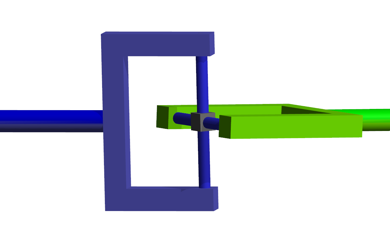
Simpler: mbs.CreateGenericJoint adds this item, with what it needs, in one call.
Interface
Python names:
ObjectJointGenericorGenericJoint, andVGenericJointfor its visualizationMarkers it acts on: those providing
PositionandOrientation: MarkerBodyRigid, MarkerNodeRigid, MarkerSuperElementRigid, MarkerKinematicTreeRigid
Parameters
The parameters of the item; in a dictionary, its type is ‘JointGeneric’:
name |
type |
size |
default |
description |
|---|---|---|---|---|
name |
String |
‘’ |
constraints’s unique name |
|
markerNumbers |
ArrayMarkerIndex |
2 |
[ invalid (-1), invalid (-1) ] |
(symbol: \([m0,m1]\tp\)) list of markers used in connector |
constrainedAxes |
ArrayIndex |
6 |
[1,1,1,1,1,1] |
(symbol: \(\jv=[j_0,\,\ldots,\,j_5]\)) flag, which determines which translation (0,1,2) and rotation (3,4,5) axes are constrained; for \(j_i\), two values are possible: 0=free axis, 1=constrained axis |
rotationMarker0 |
Matrix3D |
9 |
[[1,0,0], [0,1,0], [0,0,1]] |
(symbol: \(\LU{m0,J0}{\Rot}\)) local rotation matrix for marker \(m0\); translation and rotation axes for marker \(m0\) are defined in the local body coordinate system and additionally transformed by rotationMarker0 |
rotationMarker1 |
Matrix3D |
9 |
[[1,0,0], [0,1,0], [0,0,1]] |
(symbol: \(\LU{m1,J1}{\Rot}\)) local rotation matrix for marker \(m1\); translation and rotation axes for marker \(m1\) are defined in the local body coordinate system and additionally transformed by rotationMarker1 |
activeConnector |
Bool |
True |
flag, which determines, if the connector is active; used to deactivate (temporarily) a connector or constraint |
|
offsetUserFunctionParameters |
Vector6D |
6 |
[0.,0.,0.,0.,0.,0.] |
(symbol: \(\pv_{par}\)) vector of 6 parameters for joint’s offsetUserFunction |
offsetUserFunction |
ObjectJointGenericOffsetUserFunction |
0 |
(symbol: \(\mathrm{UF} \in \Rcal^6\)) A Python function which defines the time-dependent (fixed) offset of translation (indices 0,1,2) and rotation (indices 3,4,5) joint coordinates with parameters (mbs, t, offsetUserFunctionParameters) |
|
offsetUserFunction_t |
ObjectJointGenericOffsetUserFunction_t |
0 |
(symbol: \(\mathrm{UF} \in \Rcal^6\)) (NOT IMPLEMENTED YET)time derivative of offsetUserFunction using the same parameters |
|
alternativeConstraints |
Bool |
False |
this is an experimental flag, may change in future: if uses alternative contraint equations for rotations, currently in case of 3 locked rotations: \(\LU{0}{\tv}_{x0}\tp (\LU{0}{\tv}_{y1} \times \LU{0}{\tv}_{z0})\), \(\LU{0}{\tv}_{y0}\tp (\LU{0}{\tv}_{z1} \times \LU{0}{\tv}_{x0})\), \(\LU{0}{\tv}_{z0}\tp (\LU{0}{\tv}_{x1} \times \LU{0}{\tv}_{y0})\); this avoids 180° flips of the standard configuration in static computations, but leads to different values in Lagrange multipliers |
|
visualization |
VObjectJointGeneric |
parameters for visualization of item |
Deprecated parameters, which still work and give a DeprecationWarning when set other than their default: rotationMarker0 (deprecated since 1.12.244, removed in 2031): give the rotation to marker 0 as its localHT, e.g. MarkerBodyRigid(bodyNumber=b, localHT=exu.HT(rotation=A, translation=p)); rotationMarker1 (deprecated since 1.12.244, removed in 2031): give the rotation to marker 1 as its localHT, e.g. MarkerBodyRigid(bodyNumber=b, localHT=exu.HT(rotation=A, translation=p)).
Visualization parameters
The parameters of VObjectJointGeneric, given as visualization:
name |
type |
size |
default |
description |
|---|---|---|---|---|
show |
Bool |
True |
set true, if item is shown in visualization and false if it is not shown |
|
axesRadius |
float |
0.1 |
radius of joint axes to draw |
|
axesLength |
float |
0.4 |
length of joint axes to draw |
|
color |
Float4 |
4 |
[-1.,-1.,-1.,-1.] |
RGBA connector color; if R==-1, use default color |
Drawing
Drawn as all joints; by the free rotations: two spheres for a rigid joint, the axis as two cylinders of axesRadius and axesLength for one free rotation; with connectors.showJointAxes the frames of both markers.
Settings beyond those of all joints: connectors.jointAxesLength, connectors.jointAxesRadius, connectors.showJointAxes, general.axesTiling, general.cylinderTiling, general.sphereTiling.
Output variables
Available as OutputVariableType in sensors, Get...Output() and other functions:
output variable |
symbol |
description |
|---|---|---|
Position |
\(\LU{0}{\pv}_{m0}\) |
current global position of position marker \(m0\) |
Velocity |
\(\LU{0}{\vv}_{m0}\) |
current global velocity of position marker \(m0\) |
DisplacementLocal |
\(\LU{J0}{\Delta\pv}\) |
relative displacement in local joint0 coordinates; uses local J0 coordinates even for spherical joint configuration |
VelocityLocal |
\(\LU{J0}{\Delta\vv}\) |
relative translational velocity in local joint0 coordinates |
Rotation |
\(\LU{J0}{\ttheta}= [\theta_0,\theta_1,\theta_2]\tp\) |
relative rotation parameters (Tait Bryan Rxyz); if all axes are fixed, this output represents the rotational drift; for a revolute joint with free Z-axis, it contains the rotation in the Z-component |
AngularVelocityLocal |
\(\LU{J0}{\Delta\tomega}\) |
relative angular velocity in local joint0 coordinates; if all axes are fixed, this output represents the angular velocity constraint error; for a revolute joint, it contains the angular velocity of this axis |
ForceLocal |
\(\LU{J0}{\fv}\) |
joint force in local \(J0\) coordinates |
TorqueLocal |
\(\LU{J0}{\mv}\) |
joint torque in local \(J0\) coordinates; depending on joint configuration, the result may not be the according torque vector |
HomogeneousTransformation |
\(\LU{0}{\Hm}_{J0}\) |
the joint frame \(J0\) as homogeneous transformation: its rotation matrix and the position of marker \(m0\), as 4x4 matrix \([\LU{0}{\Rot}_{J0}\;\LU{0}{\pv}_{m0};\;\Null\tp\;1]\); the Get…Output functions return it as exu.HT, a sensor stores its 16 values row by row |
HomogeneousTransformationLocal |
\(\LU{J0}{\Hm}_{J1} = \LU{0}{\Hm}_{J0}^{-1}\,\LU{0}{\Hm}_{J1}\) |
the joint frame \(J1\) relative to the joint frame \(J0\): the relative rotation matrix \(\LU{0}{\Rot}_{J0}\tp\LU{0}{\Rot}_{J1}\) and the relative position \(\LU{0}{\Rot}_{J0}\tp(\LU{0}{\pv}_{m1}-\LU{0}{\pv}_{m0})\); for a joint the identity up to its free axes and its drift; returned and stored as HomogeneousTransformation |
Detailed description
Definition of quantities
intermediate variables |
symbol |
description |
|---|---|---|
marker m0 position |
\(\LU{0}{\pv}_{m0}\) |
current global position which is provided by marker m0 |
marker m0 orientation |
\(\LU{0,m0}{\Rot}\) |
current rotation matrix provided by marker m0 |
joint J0 orientation |
\(\LU{0,J0}{\Rot} = \LU{0,m0}{\Rot} \LU{m0,J0}{\Rot}\) |
joint \(J0\) rotation matrix |
joint J0 orientation vectors |
\(\LU{0,J0}{\Rot} = [\LU{0}{\tv_{x0}},\,\LU{0}{\tv_{y0}},\,\LU{0}{\tv_{z0}}]\tp\) |
orientation vectors (represent local \(x\), \(y\), and \(z\) axes) in global coordinates, used for definition of constraint equations |
marker m1 position |
\(\LU{0}{\pv}_{m1}\) |
accordingly |
marker m1 orientation |
\(\LU{0,m1}{\Rot}\) |
current rotation matrix provided by marker m1 |
joint J1 orientation |
\(\LU{0,J1}{\Rot} = \LU{0,m1}{\Rot} \LU{m1,J1}{\Rot}\) |
joint \(J1\) rotation matrix |
joint J1 orientation vectors |
\(\LU{0,J1}{\Rot} = [\LU{0}{\tv_{x1}},\,\LU{0}{\tv_{y1}},\,v\tv_{z1}]\tp\) |
orientation vectors (represent local \(x\), \(y\), and \(z\) axes) in global coordinates, used for definition of constraint equations |
marker m0 velocity |
\(\LU{0}{\vv}_{m0}\) |
current global velocity which is provided by marker m0 |
marker m1 velocity |
\(\LU{0}{\vv}_{m1}\) |
accordingly |
marker m0 velocity |
\(\LU{b}{\tomega}_{m0}\) |
current local angular velocity vector provided by marker m0 |
marker m1 velocity |
\(\LU{b}{\tomega}_{m1}\) |
current local angular velocity vector provided by marker m1 |
Displacement |
\(\LU{0}{\Delta\pv}=\LU{0}{\pv}_{m1} - \LU{0}{\pv}_{m0}\) |
used, if all translational axes are constrained |
Velocity |
\(\LU{0}{\Delta\vv} = \LU{0}{\vv}_{m1} - \LU{0}{\vv}_{m0}\) |
used, if all translational axes are constrained (velocity level) |
DisplacementLocal |
\(\LU{J0}{\Delta\pv}\) |
\(\left(\LU{0,m0}{\Rot}\LU{m0,J0}{\Rot}\right)\tp \LU{0}{\Delta\pv}\) |
VelocityLocal |
\(\LU{J0}{\Delta\vv}\) |
\(\left(\LU{0,m0}{\Rot}\LU{m0,J0}{\Rot}\right)\tp \LU{0}{\Delta\vv}\) \(\ldots\) note that this is the global relative velocity projected into the local \(J0\) coordinate system |
AngularVelocityLocal |
\(\LU{J0}{\Delta\omega}\) |
\(\left(\LU{0,m0}{\Rot}\LU{m0,J0}{\Rot}\right)\tp \left( \LU{0,m1}{\Rot} \LU{m1}{\omega} - \LU{0,m0}{\Rot} \LU{m0}{\omega} \right)\) |
algebraic variables |
\(\zv=[\lambda_0,\,\ldots,\,\lambda_5]\tp\) |
vector of algebraic variables (Lagrange multipliers) according to the algebraic equations |
Connector constraint equations
Equations for translational part (activeConnector = True):
If \([j_0,\,\ldots,\,j_2] = [1,1,1]\tp\), meaning that all translational coordinates are fixed, the translational index 3 constraints read (\(UF_{0,1,2}(mbs, t, \pv_{par})\) is the translational part of the user function \(UF\)),
and the translational index 2 constraints read
and iN represents the itemNumber (=objectNumber).
If \([j_0,\,\ldots,\,j_2] \neq [1,1,1]\tp\), meaning that at least one translational coordinate is free, the translational index 3 constraints read for every component \(k \in [0,1,2]\) of the vector \(\LU{J0}{\Delta\pv}\)
and the translational index 2 constraints read for every component \(k \in [0,1,2]\) of the vector \(\LU{J0}{\Delta\vv}\)
Equations for rotational part (activeConnector = True):
The following equations are exemplarily for certain constrained rotation axes configurations, which shall represent all other possibilities. Note that the axes are always given in global coordinates, compare the table in Definition of quantities.
Equations are only given for the index 3 case; the index 2 case can be derived from these equations easily (see C++ code…). In case of user functions, the additional rotation matrix \(\LU{J0,J0U}{\Rot}(UF_{3,4,5}(mbs, t, \pv_{par}))\), in which the three components of \(UF_{3,4,5}\) are interpreted as Tait-Bryan angles that are added to the joint frame.
If 3 rotation axes are constrained (e.g., translational or planar joint), \([j_3,\,\ldots,\,j_5] = [1,1,1]\tp\), the index 3 constraint equations read
If 2 rotation axes are constrained (revolute joint), e.g., \([j_3,\,\ldots,\,j_5] = [0,1,1]\tp\), the index 3 constraint equations read
If 1 rotation axis is constrained (universal joint), e.g., \([j_3,\,\ldots,\,j_5] = [1,0,0]\tp\), the index 3 constraint equations read
if activeConnector = False,
Userfunction: offsetUserFunction(mbs, t, itemNumber, offsetUserFunctionParameters)
A user function, which computes scalar offset for relative joint translation and joint rotation for the GenericJoint,
e.g., in order to move or rotate a body on a prescribed trajectory.
It is NECESSARY to use sufficiently smooth functions, having initial offsets consistent with initial configuration of bodies,
either zero or compatible initial offset-velocity, and no initial accelerations.
The offsetUserFunction is ONLY used in case of static computation or index3 (generalizedAlpha) time integration.
In order to be on the safe side, provide both offsetUserFunction and offsetUserFunction_t.
Note that itemNumber represents the index of the object in mbs, which can be used to retrieve additional data from the object through
mbs.GetObjectParameter(itemNumber, ...), see the according description of GetObjectParameter.
The user function gets time and the offsetUserFunctionParameters as an input and returns the computed offset vector for all relative translational and rotational joint coordinates:
arguments / return |
type or size |
description |
|---|---|---|
|
MainSystem |
provides MainSystem mbs in which underlying item is defined |
|
Real |
current time in mbs |
|
Index |
integer number of the object in mbs, allowing easy access to all object data via mbs.GetObjectParameter(itemNumber, …) |
|
Vector6D |
\(\pv_{par}\), set of parameters which can be freely used in user function |
return value |
Vector6D |
computed offset vector for given time |
Userfunction: offsetUserFunction_t(mbs, t, itemNumber, offsetUserFunctionParameters)
A user function, which computes an offset velocity vector for the GenericJoint.
It is NECESSARY to use sufficiently smooth functions, having initial offset velocities consistent with initial velocities of bodies.
The offsetUserFunction_t is used instead of offsetUserFunction in case of velocityLevel = True,
or for index2 time integration and needed for computation of initial accelerations in second order implicit time integrators.
Note that itemNumber represents the index of the object in mbs, which can be used to retrieve additional data from the object through
mbs.GetObjectParameter(itemNumber, ...), see the according description of GetObjectParameter.
The user function gets time and the offsetUserFunctionParameters as an input and returns the computed offset velocity vector for all relative translational and rotational joint coordinates:
arguments / return |
type or size |
description |
|---|---|---|
|
MainSystem |
provides MainSystem mbs in which underlying item is defined |
|
Real |
current time in mbs |
|
Index |
integer number of the object in mbs, allowing easy access to all object data via mbs.GetObjectParameter(itemNumber, …) |
|
Vector6D |
\(\pv_{par}\), set of parameters which can be freely used in user function |
return value |
Vector6D |
computed offset velocity vector for given time |
Example:
#simple example, computing only the translational offset for x-coordinate
from math import sin, cos, pi
def UFoffset(mbs, t, itemNumber, offsetUserFunctionParameters):
    return [offsetUserFunctionParameters[0]*(1 - cos(t*10*2*pi)), 0,0,0,0,0]
Mini example
#a joint whose constrained axes are chosen: here all but the rotation about z - a revolute joint -
#holding a rigid body pendulum at its end
inertia = InertiaCuboid(density=1000, sideLengths=[1,0.1,0.1])
node = mbs.AddNode(NodeRigidBodyEP(referenceCoordinates=[0.5,0,0]+eulerParameters0))
body = mbs.AddObject(ObjectRigidBody(nodeNumber=node, mass=inertia.Mass(), inertia=inertia.GetInertia6D()))
mbs.AddLoad(LoadMassProportional(markerNumber=mbs.AddMarker(MarkerBodyMass(bodyNumber=body)), loadVector=[0,-9.81,0]))
mGround = mbs.AddMarker(MarkerBodyRigid(bodyNumber=oGround, localPosition=[0,0,0]))
mBody = mbs.AddMarker(MarkerBodyRigid(bodyNumber=body, localPosition=[-0.5,0,0]))
mbs.AddObject(ObjectJointGeneric(markerNumbers=[mGround, mBody], constrainedAxes=[1,1,1, 1,1,0]))

mbs.Assemble()
simulationSettings = exu.SimulationSettings()
simulationSettings.timeIntegration.numberOfSteps = 1000
mbs.SolveDynamic(simulationSettings)

#the pendulum falls from horizontal; the angle after 1 second (numerical)
exu.sys['testResult'] = mbs.GetNodeOutput(node, exu.OutputVariableType.Rotation)[2]
Examples (Ex) and TestModels (TM) that show this item, with weblink to github: tutorialRigidBody.py (Ex), fourBarMechanism3D.py (Ex), genericJointUserFunctionTest.py (TM)